In order to test MIT Motorsport's Custom high power inverter at load, we needed a dynamometer to provide a load. Ideally, we needed a torque transducer as well to determine torque output, however, due to timeline constraints in acquiring a transducer, we decided to build two Dynos: a simple load dyno for initial testing, and eventually, a secondary dyno with a transducer for tuning controls. I was the RE for Dyno I, the basic load Dyno. I also helped mentor Vaughn Khouri in the development of Dyno II, which he has written extensively about here.
Credit to Liong Ma for the design of the custom inverter, and Huge thanks to Cali Hendricks for helping with the machining of the Dyno.
My Dynamometer I CDR can be found here.

A Cross sectional view of the first Dyno.
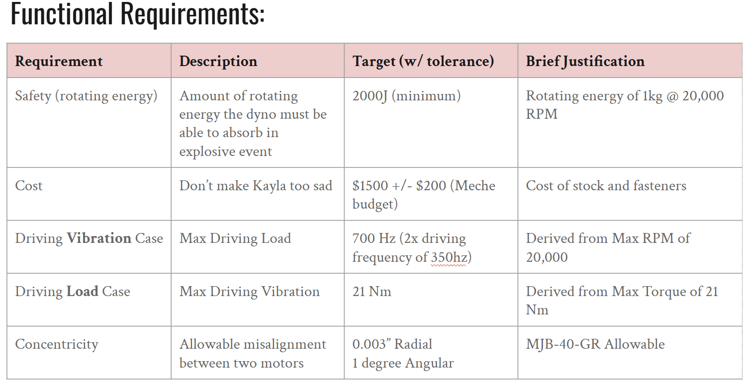
The project first began with defining functional requirements. We decided to feed two AMK DD5 motors into each other, which are the motors we had used in MY25 for our in hub gearboxes. The AMKs are a 20 kW motor that can easily exceed 21,000 RPM, which contributed to the potential danger of the system.
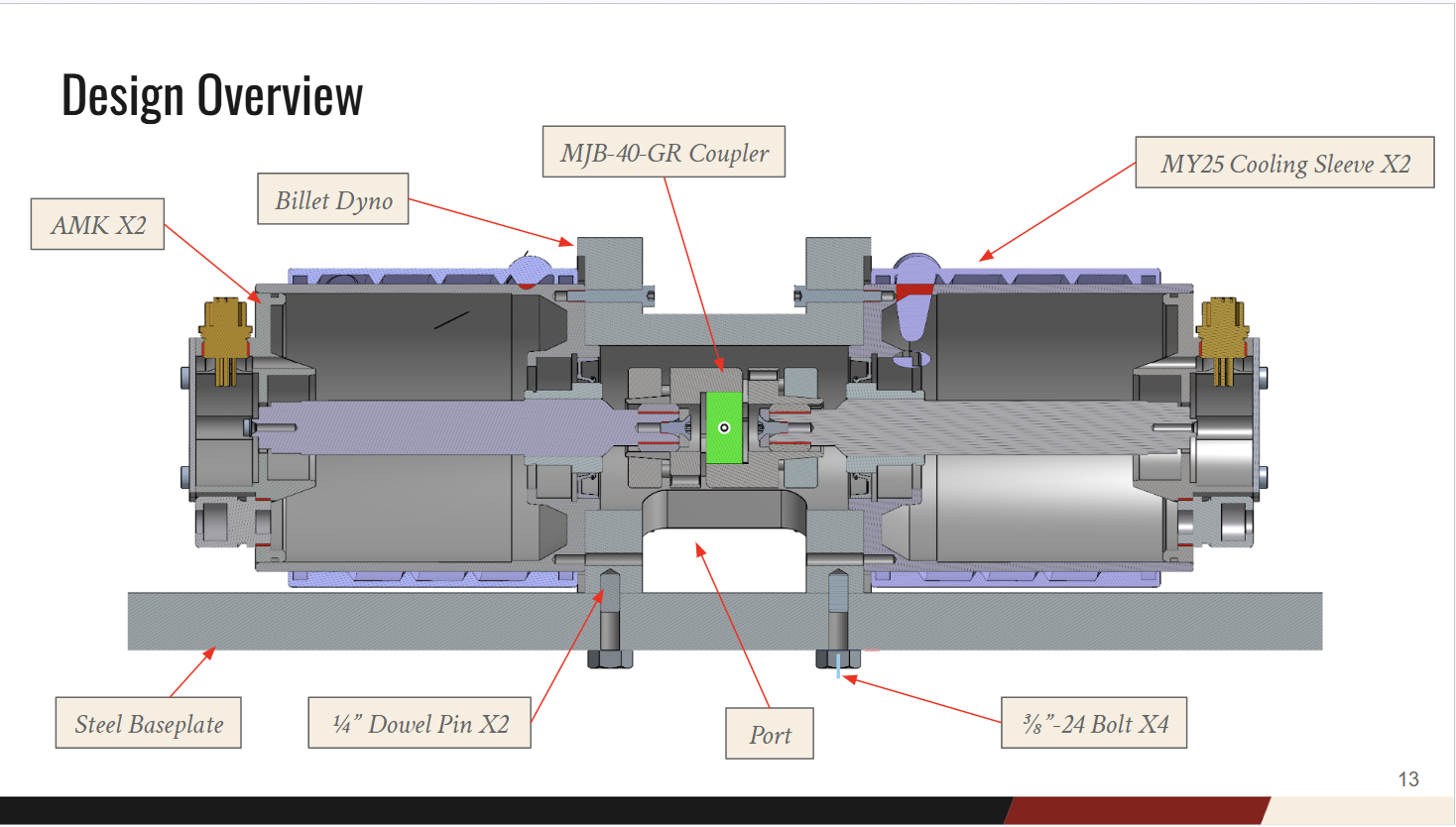
The only coupler we could find that could handle the high speed and torque requirements of the AMKs (at a reasonable price) was the MJB-40-GR clamping coupler. However, this coupler had a fairly tight radial misalignment allowable at 0.003 in. As a result, I decided to make a single piece monolithic "upright" of sorts to connect everything together. This allowed the critical bores to be manufactured in one go on a lathe, minimizing the tolerance stackup. A bonus feature was that the entire system would be enclosed, minimizing the risk of a failure launching shrapnel everywhere.
Additionally, the output of the AMK motors feed into a DIN 5480 spline (these motors are German after all). This necessitated a spline adapter to allow us to clamp onto a round output shaft. We decided to have these wire EDM cut in house.
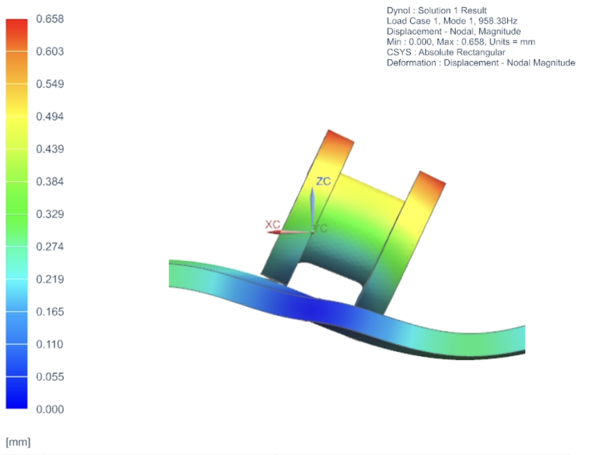
As the main load case for the dyno was vibrational, I ran a modal analysis utilizing NX Simcenter's SOL103 Real Eigenvalues. I modeled the baseplate as CTETRA4 elements, and the Upright itself as CTETRA10 elements, connected by a series of CBUSHES to represent bolted joints and dowel pins. The baseplate was assumed to be pinned at six points to account for the baseplate being clamped down. The first mode was foudn to be 958 Hz, which was well in excess of our requirement of 750 Hz.
In hindsight, I would have modeled this quite differently. Firstly, the mass of the motors is quite significant, and I likely should have modeled those as point masses connected by an RBE2 to Cbushes representing the motor bolts. Additionally, the baseplate should have simply been modeled as a 2D sheet element, which would help reduce runtimes.
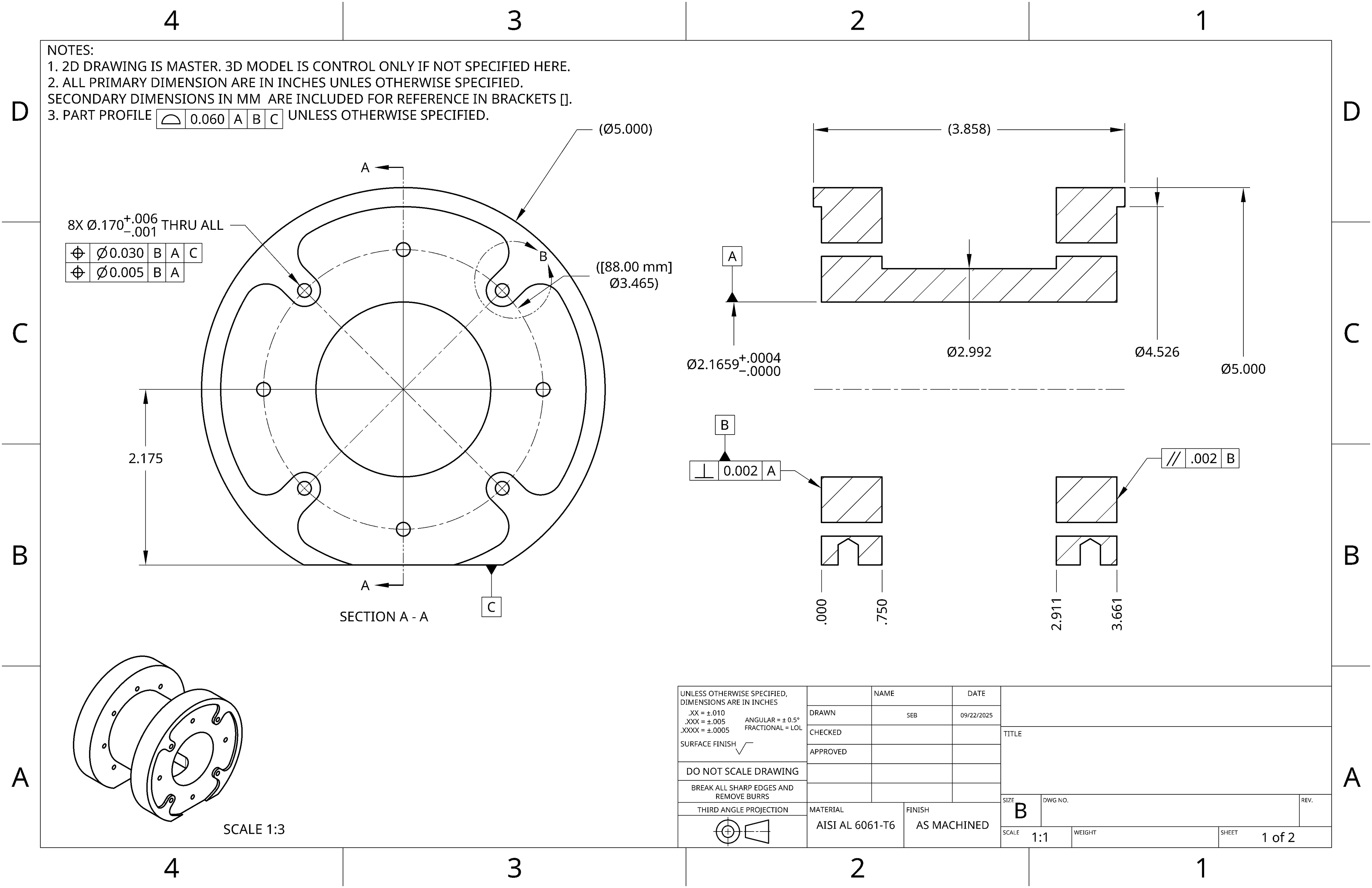
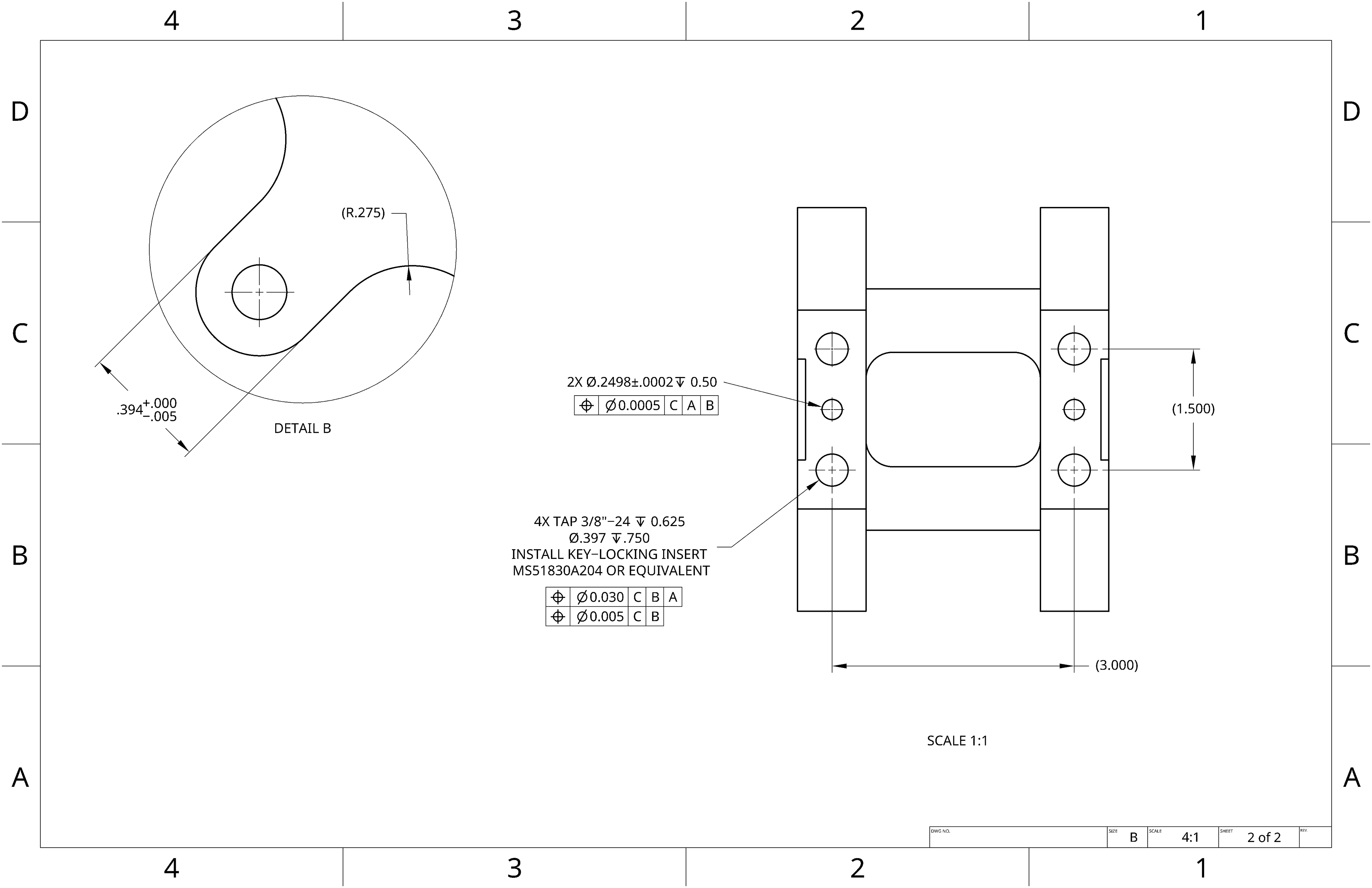
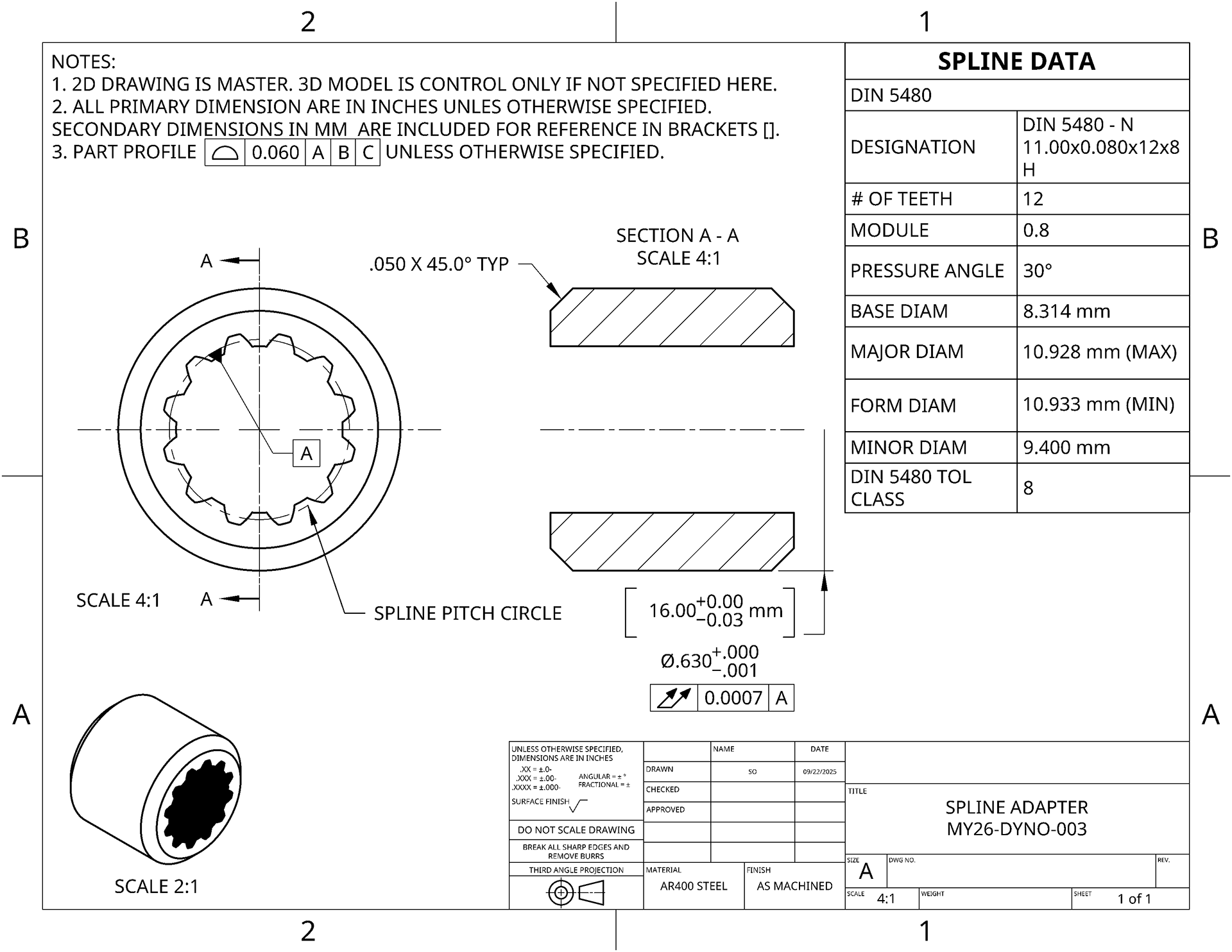
I then moved onto creating engineering drawings for the parts we had to make in house. While I typically draft in Siemens NX, I instead had to use Onshape due to our license/Teamcenter server literally exploding.
The tolerances were determined based on a tolerance budget. As the coupler allowed 0.003" of radial misalignment, I budgeted 0.0015" to the adapter, 0.0007" to the misalignment from the bore, and 0.0007" to the misalignment from flatness of the mounting faces, resulting in the tolerances in the drawing. These drawings were internal, so they lack some of the detail I put into drawings that I send out.
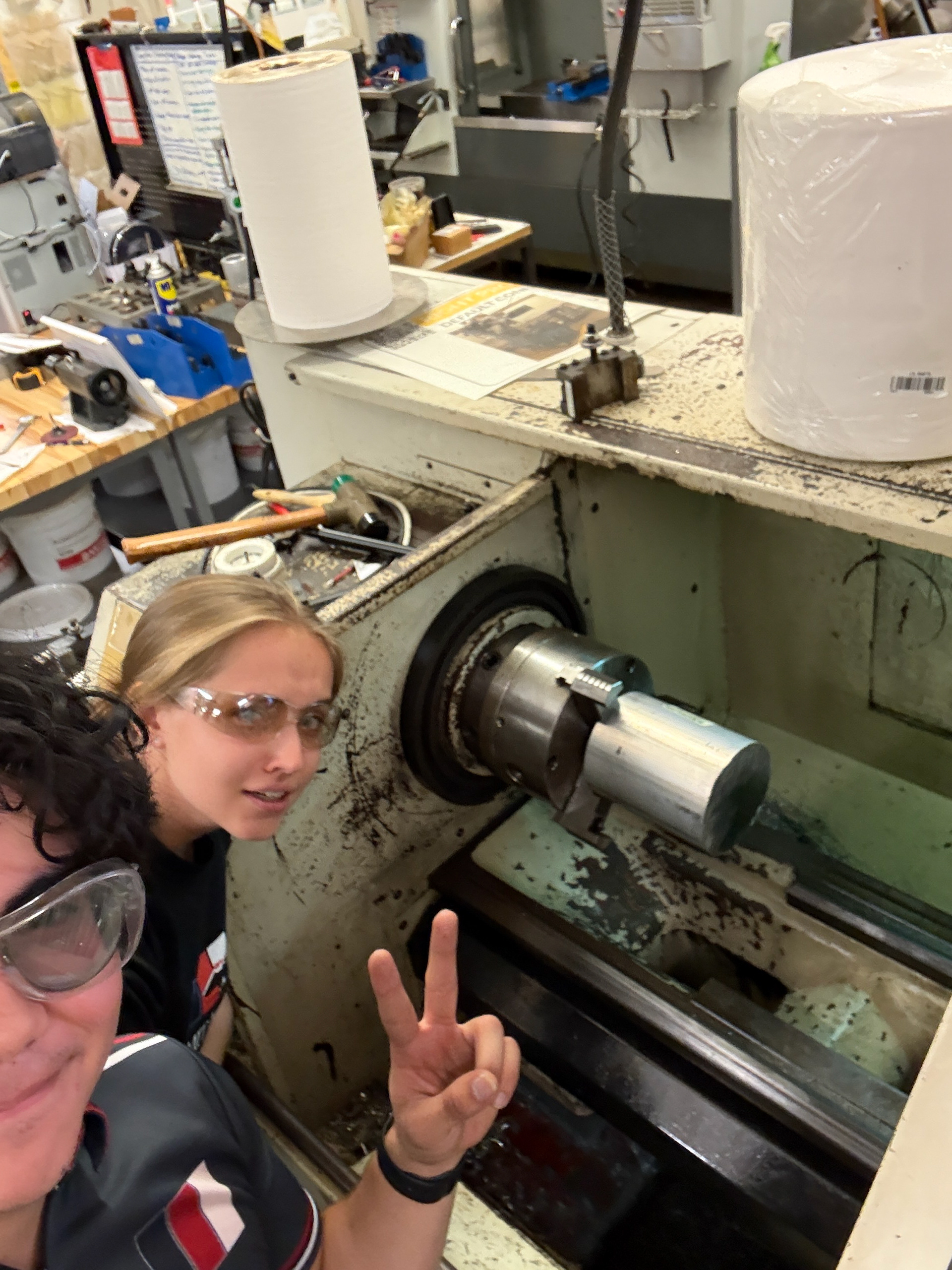
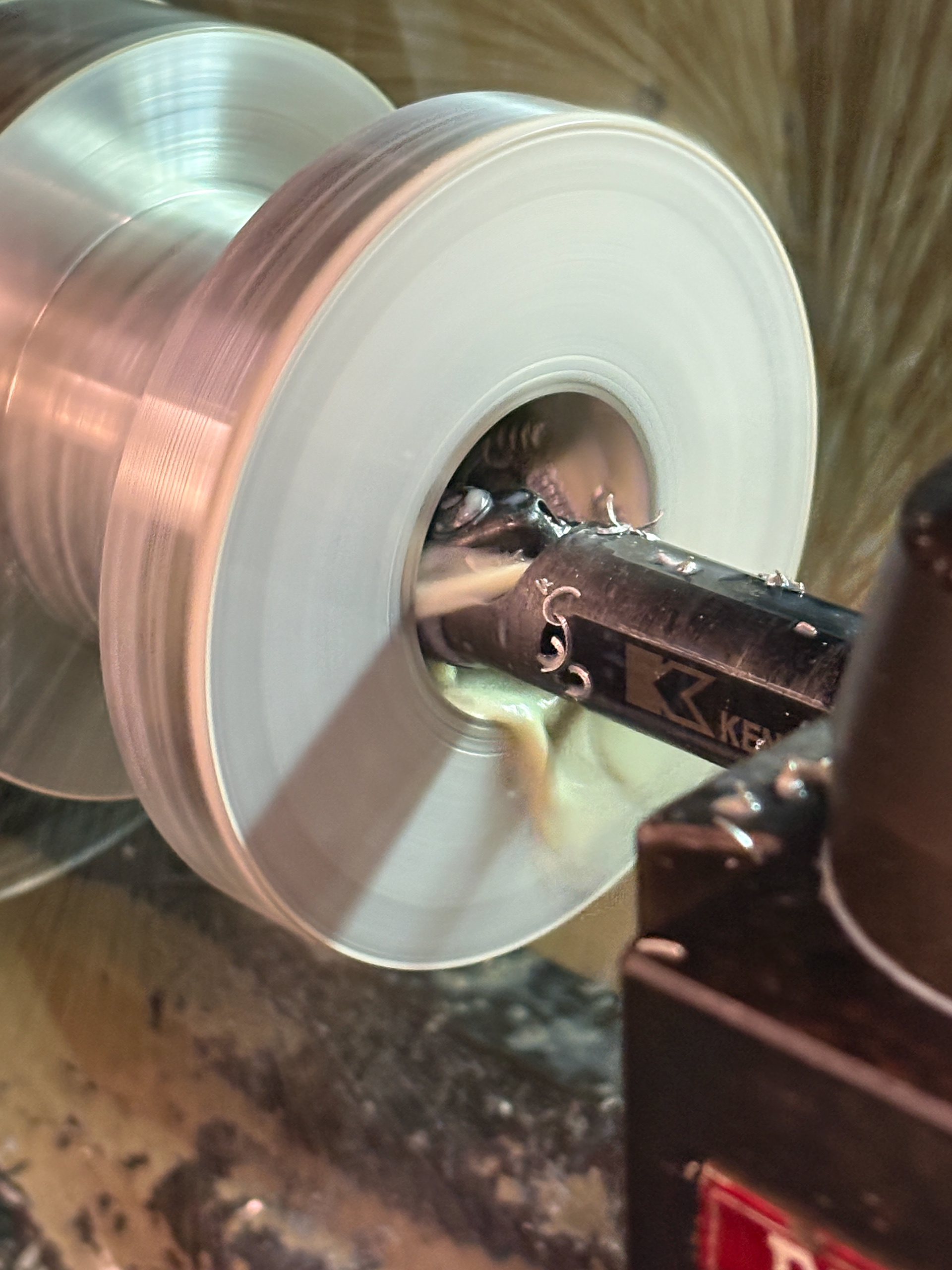
From there, we moved onto manufacturing the upright from a massive piece of round stock. The first operations were done on the lathe to ensure the central bore was straight and round. Huge credit to Cali for hogging away a ridiculous amount of material.
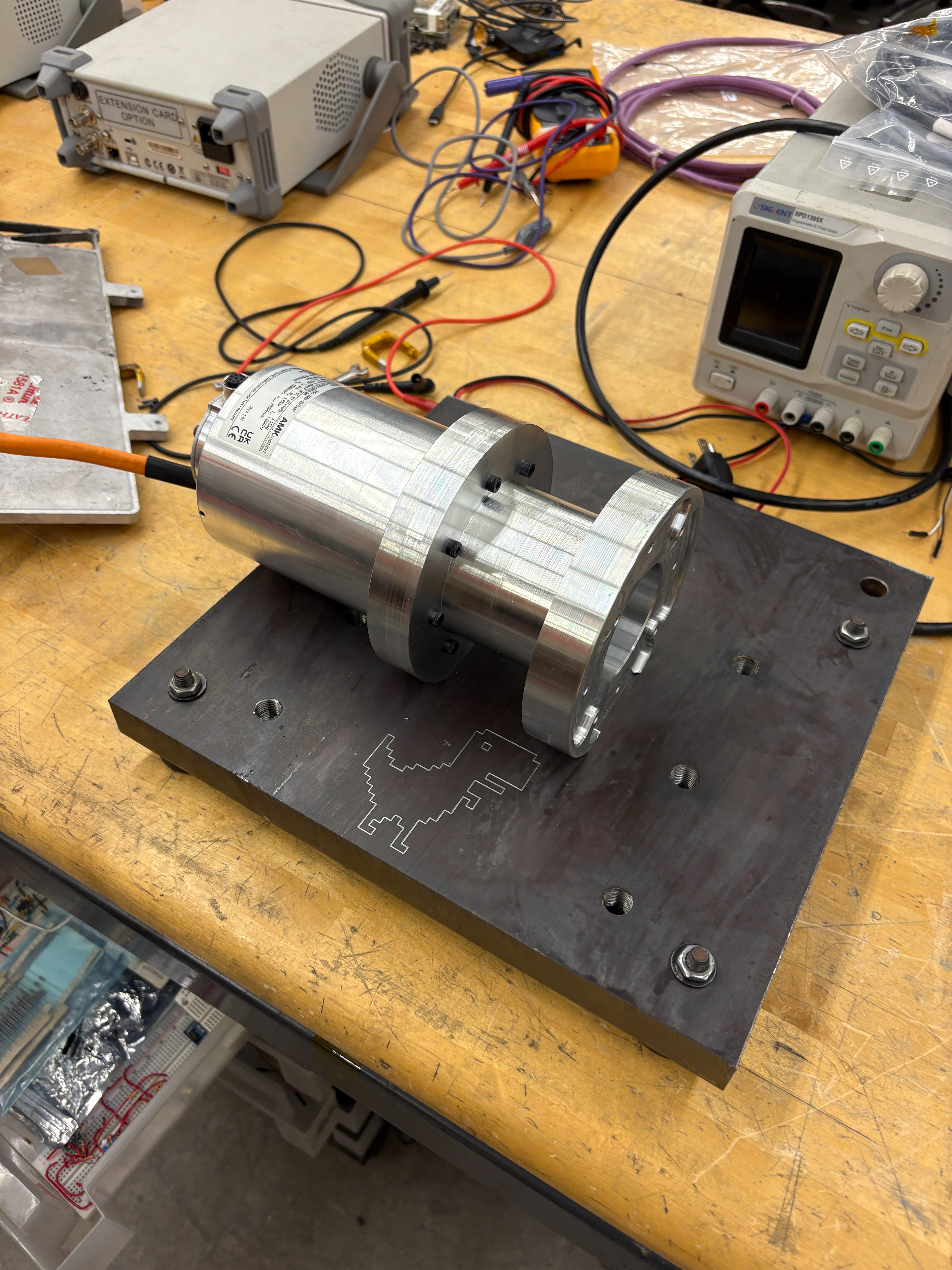
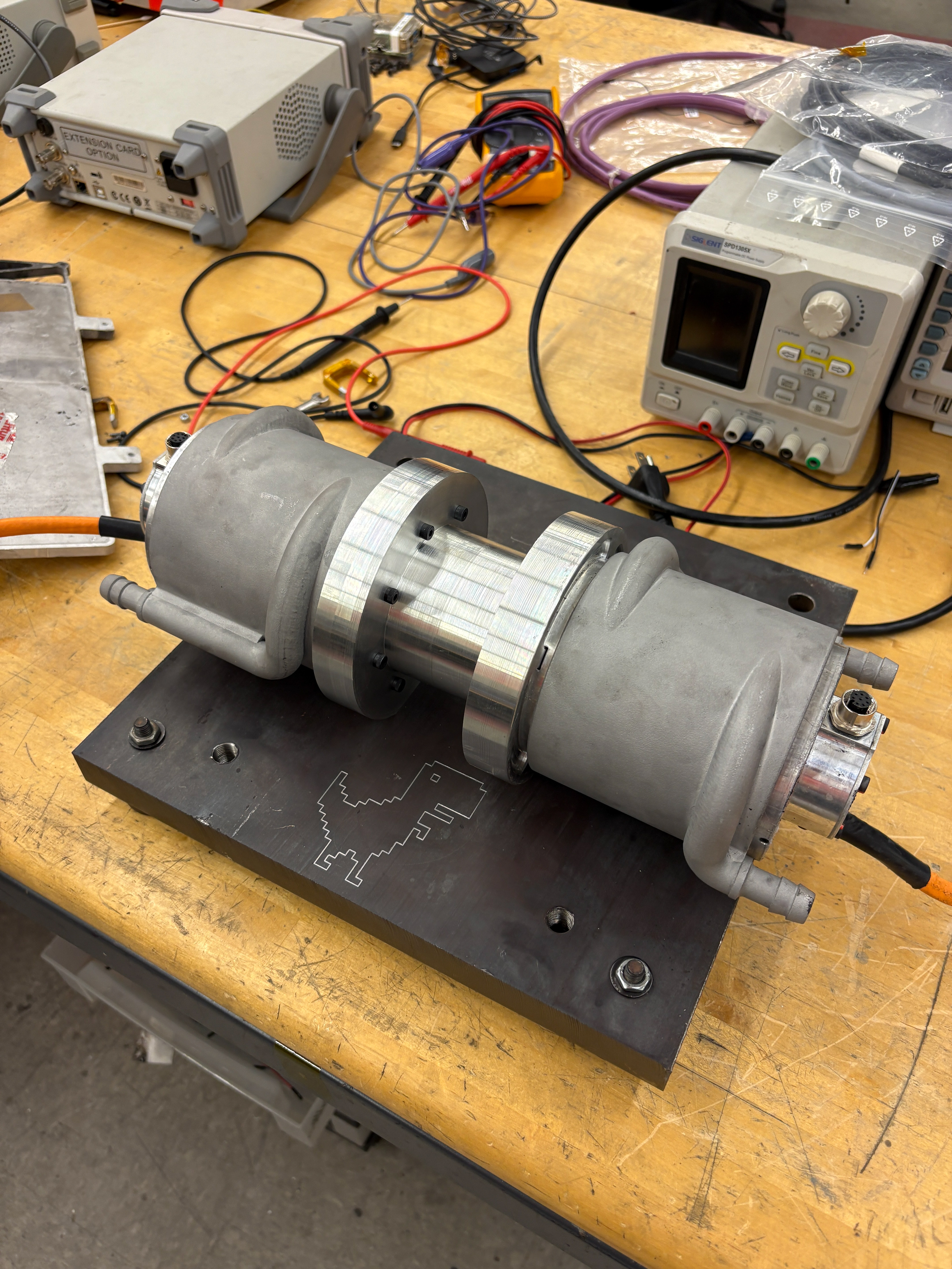
Once all of the parts were machined, we assembled them with leftover cooling sleeves from MY25's gearbox. It did, in fact, not resonate, and worked well for a few months while Dyno II was designed and came online.