In the Spring of 2026, we experienced severe delays in the procurement of our uprights as well as other outsourced parts. A quoted 4-6 lead time became 8, and then 10, and at some point, we were at risk of not being able to attend the Formula Hybrid + Electric Competition in Loudon, NH.
As a result, I came up with a backup plan. I would make new weldment uprights as fast as possible to enable us to drive and compete while we waiting on the uprights to ship and clear customs in Anchorage. In the end, it took a consecutive week of 16 hour workdays, but it got done. Huge thanks to Jeiven Figueroa '28 for helping me waterjet plates for a day straight, and Mia Chen '27 for spending an unhealthy amount of hours welding these.
Presenting: Project Hail Mary.
As a result, I came up with a backup plan. I would make new weldment uprights as fast as possible to enable us to drive and compete while we waiting on the uprights to ship and clear customs in Anchorage. In the end, it took a consecutive week of 16 hour workdays, but it got done. Huge thanks to Jeiven Figueroa '28 for helping me waterjet plates for a day straight, and Mia Chen '27 for spending an unhealthy amount of hours welding these.
Presenting: Project Hail Mary.
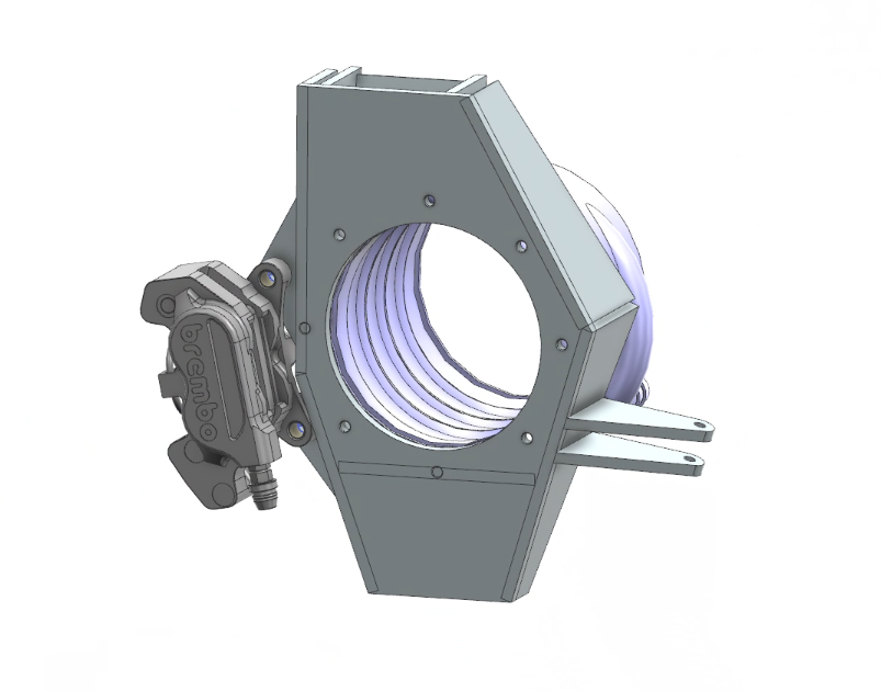
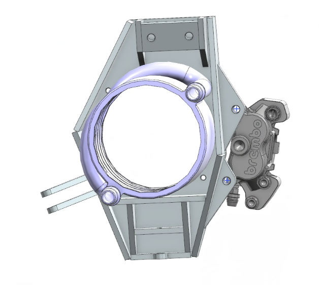
I began with designing the front uprights in Siemens NX. The idea was simple: Utilize tab and slot geometry to design an upright that was easy to manufacture using a waterjet and easy to jig and weld. The goal was not to be light, but to exist. As the proper MY26 uprights had cooling sleeve channels machined in, I also had to work to adapt the separate cooling sleeves from MY25 to package, and create new brake mounting.
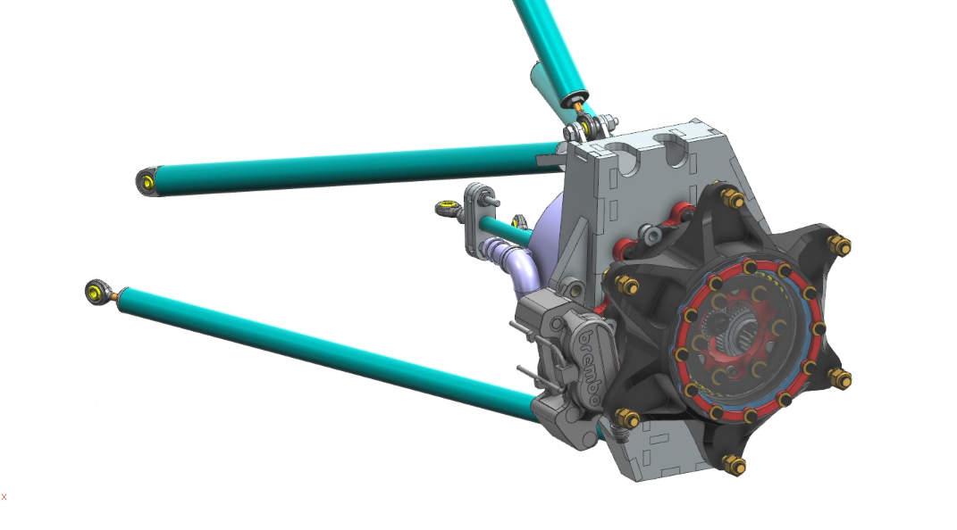
The front Fake upright in the context of the gearbox and suspension. Sticks out like a sore thumb doesn't it?
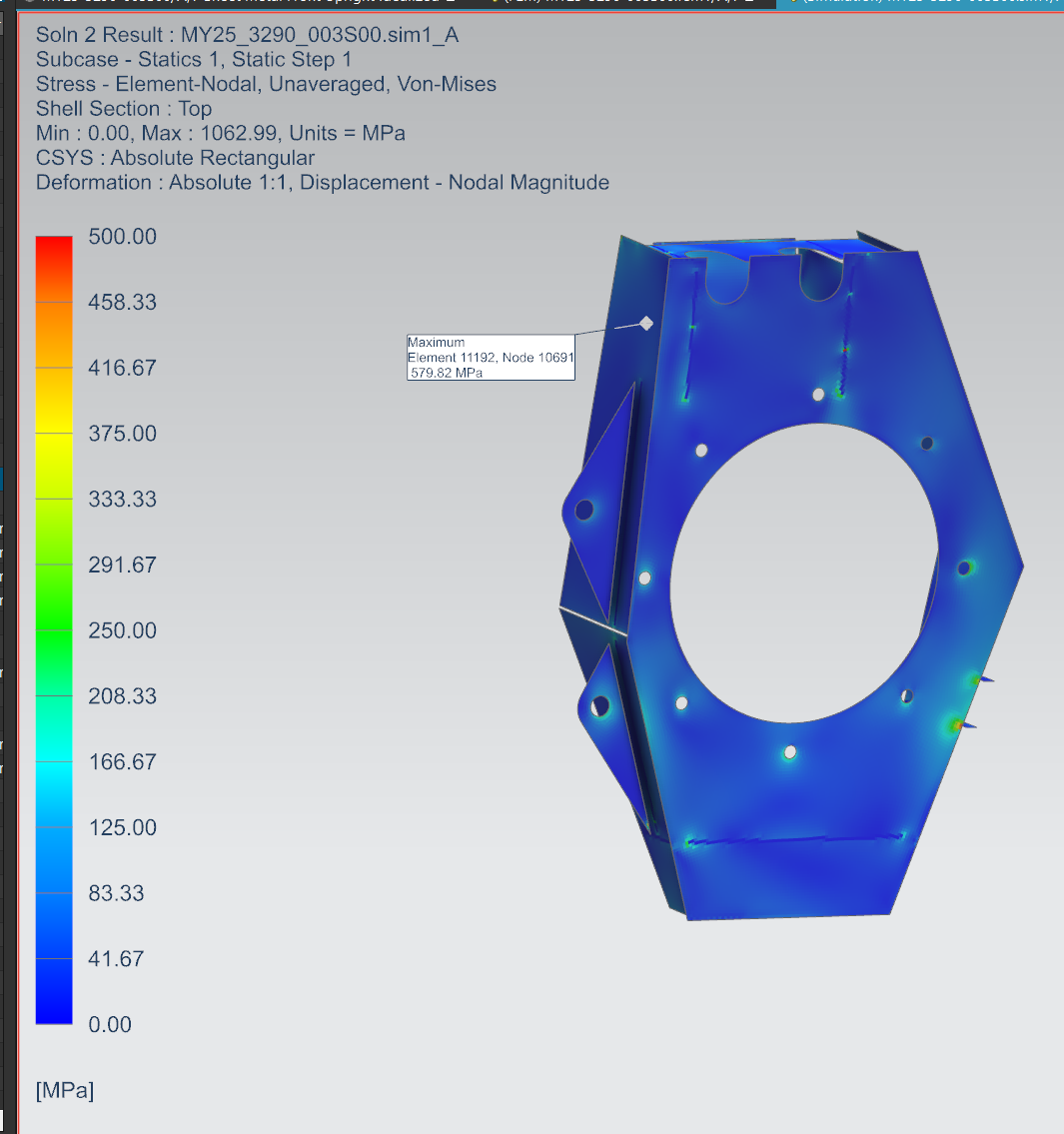
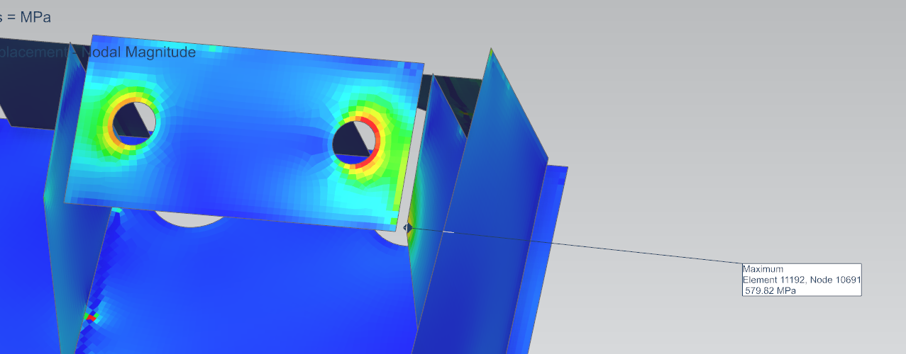
Once I had a basic design thrown together, I moved onto FEA to make sure this thing would survive. We decided to make the structure out of annealed 4130 Sheet steel, as it was easy to weld and still fairly strong, with a yield strength of ~450 MPa, or 65 KSI. Additionally, this would allow us to care a bit less about the welding heat affected zone (HAZ) reducing our yield strength.
As I had never done a weldment FEA before this, I initially modeled the upright using sheet bodies with RBE2s to represent welds. This was enough to reveal unideal load paths in my first run of the design, especially around the mount for the Camber Clevis.
In hindsight, I would have extended the sheet bodies and used stitch edge, but at the time I was unaware that tool existed.
In hindsight, I would have extended the sheet bodies and used stitch edge, but at the time I was unaware that tool existed.
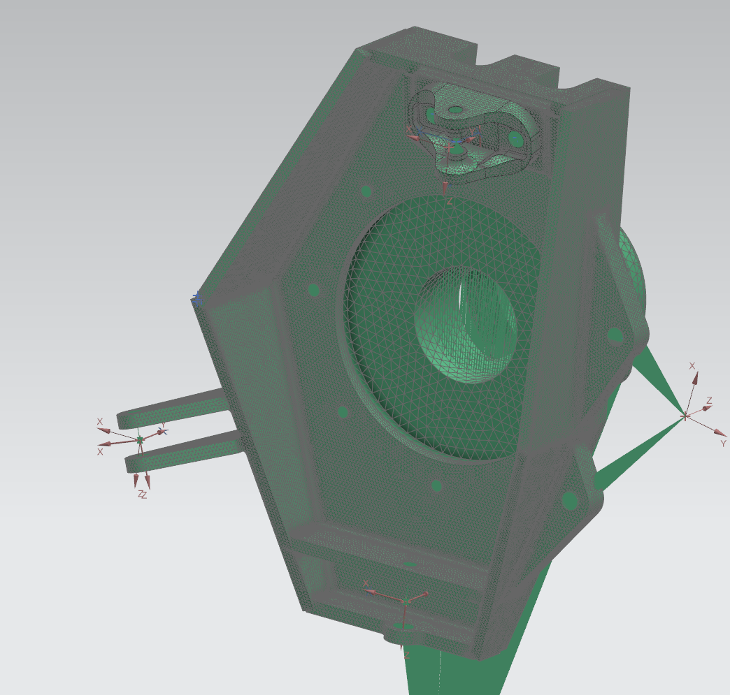

Due to team concerns about stress concentrations in the upright and properly modeling weld fillets, I switched to a 3D representation of the upright in FEM, and continued down that path. This was somewhat inefficient, as each run took about 45 minutes to compute. I also took the liberty of improving the load paths considerably.
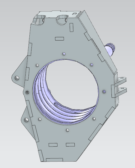
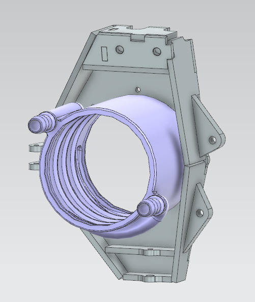
Once the fronts were close to finished, I moved on to creating the rear uprights with similar load paths and plate design.
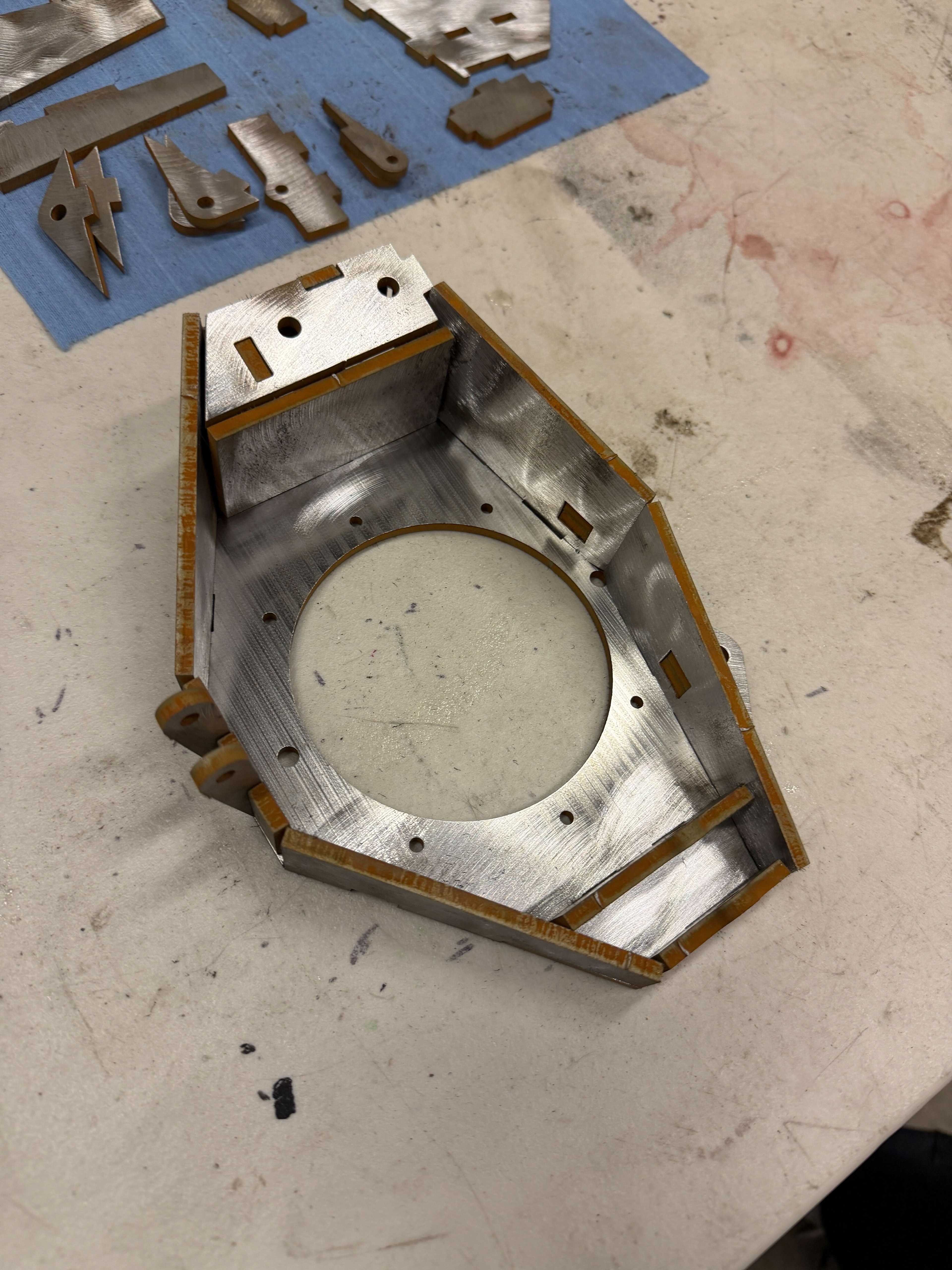
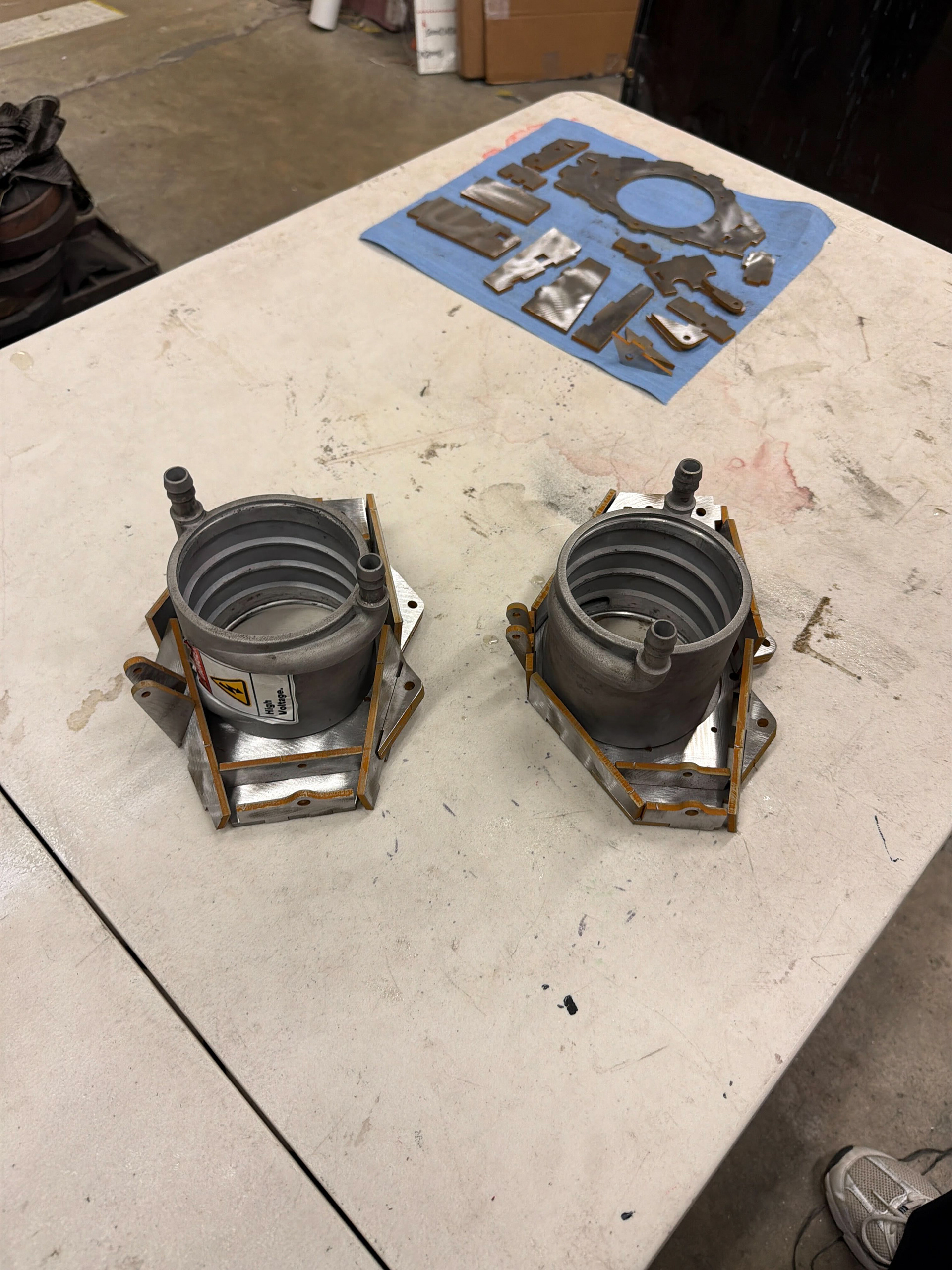
Once we closed the design in FEA, we immediately went down to the waterjet to cut out the plates. I first created a test part to spec how much of an offset we would need for the tab and slots to fit together nicely, as our timeline literally did not allow for time to grind the tabs. In the end, it all fit together quite nicely.

Jeiven and I after assembling the first upright. Morale began to improve right around here.
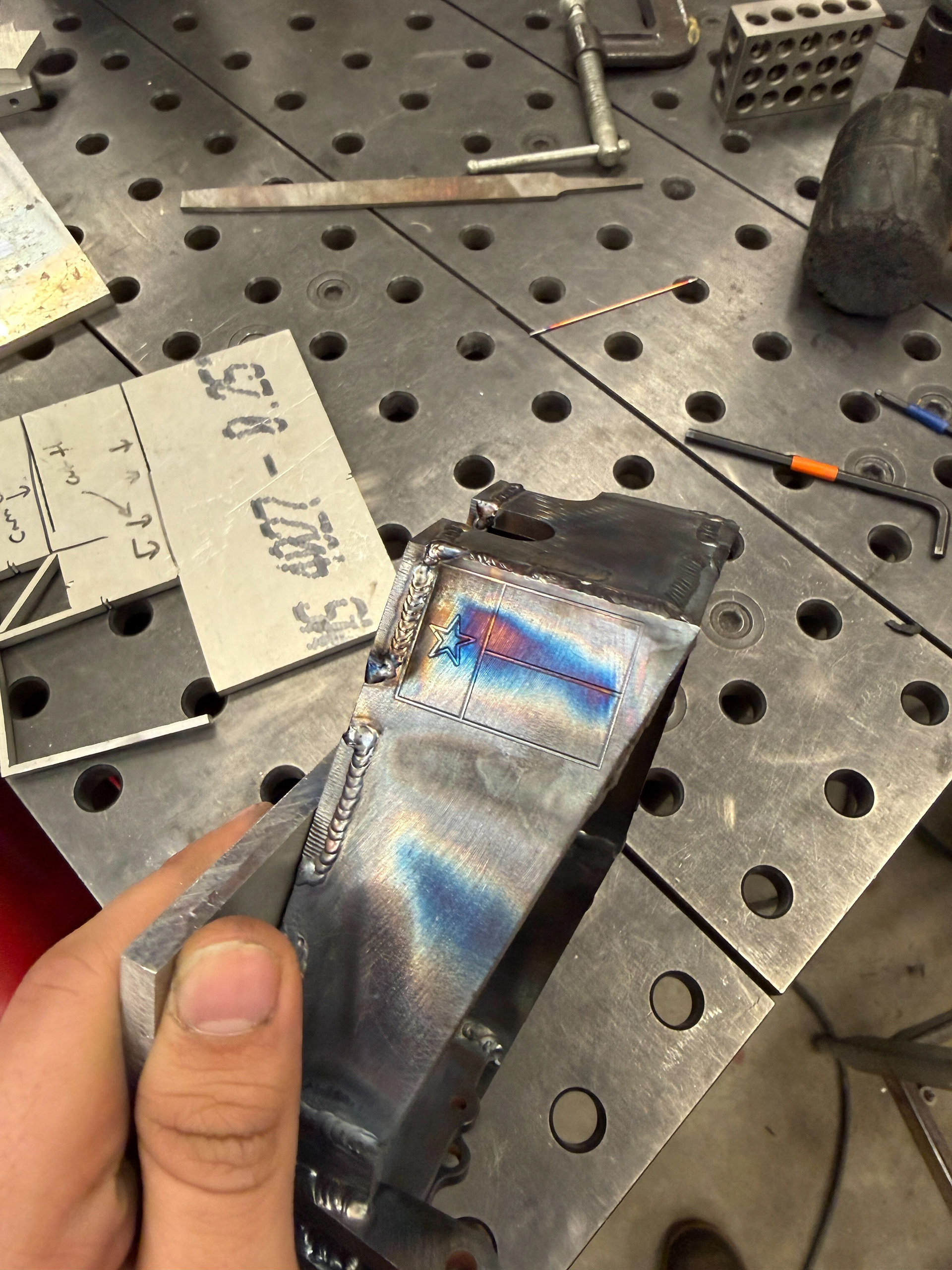
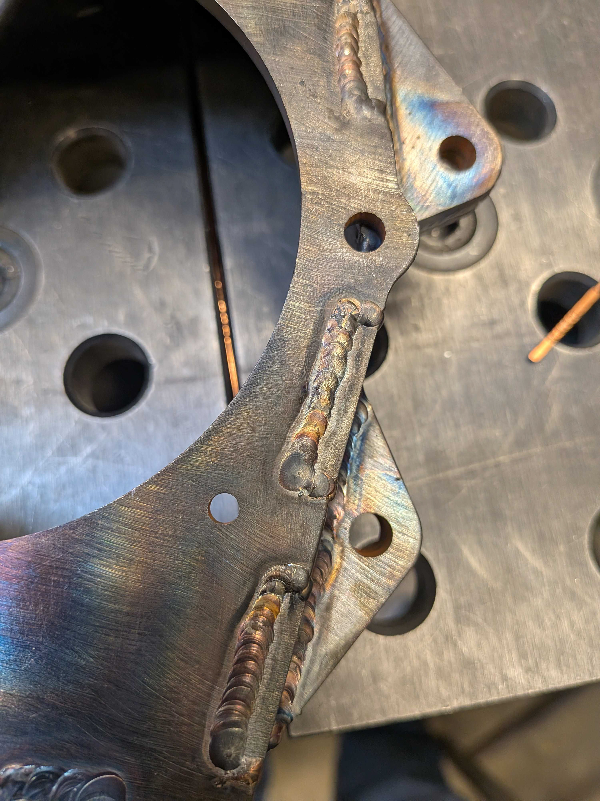
After this we (Mia) began to weld together the uprights. I also added a bit of a flair to the design myself, because no one could stop me.
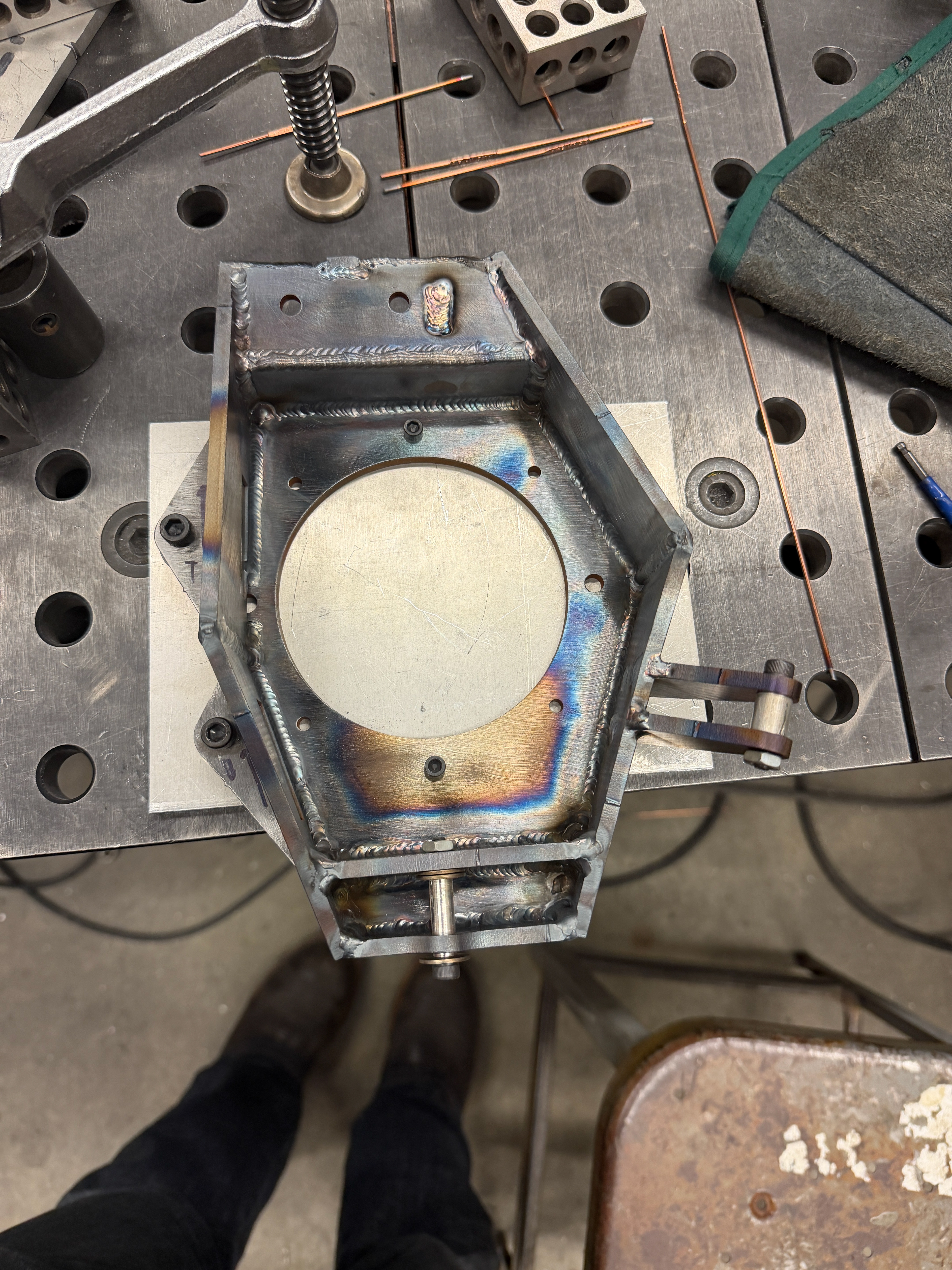
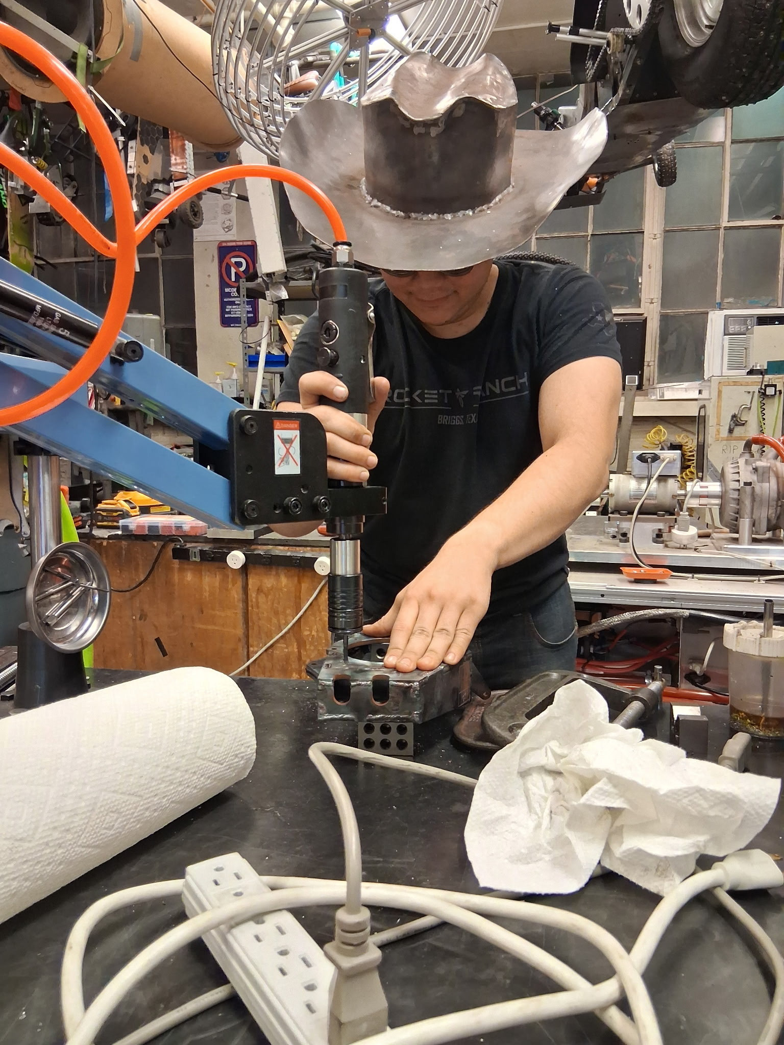
One of the jigs used to weld the fronts. Afterwards, we did some postmachining to tap and ream holes. The Steel Cowboy hat was mandatory PPE.
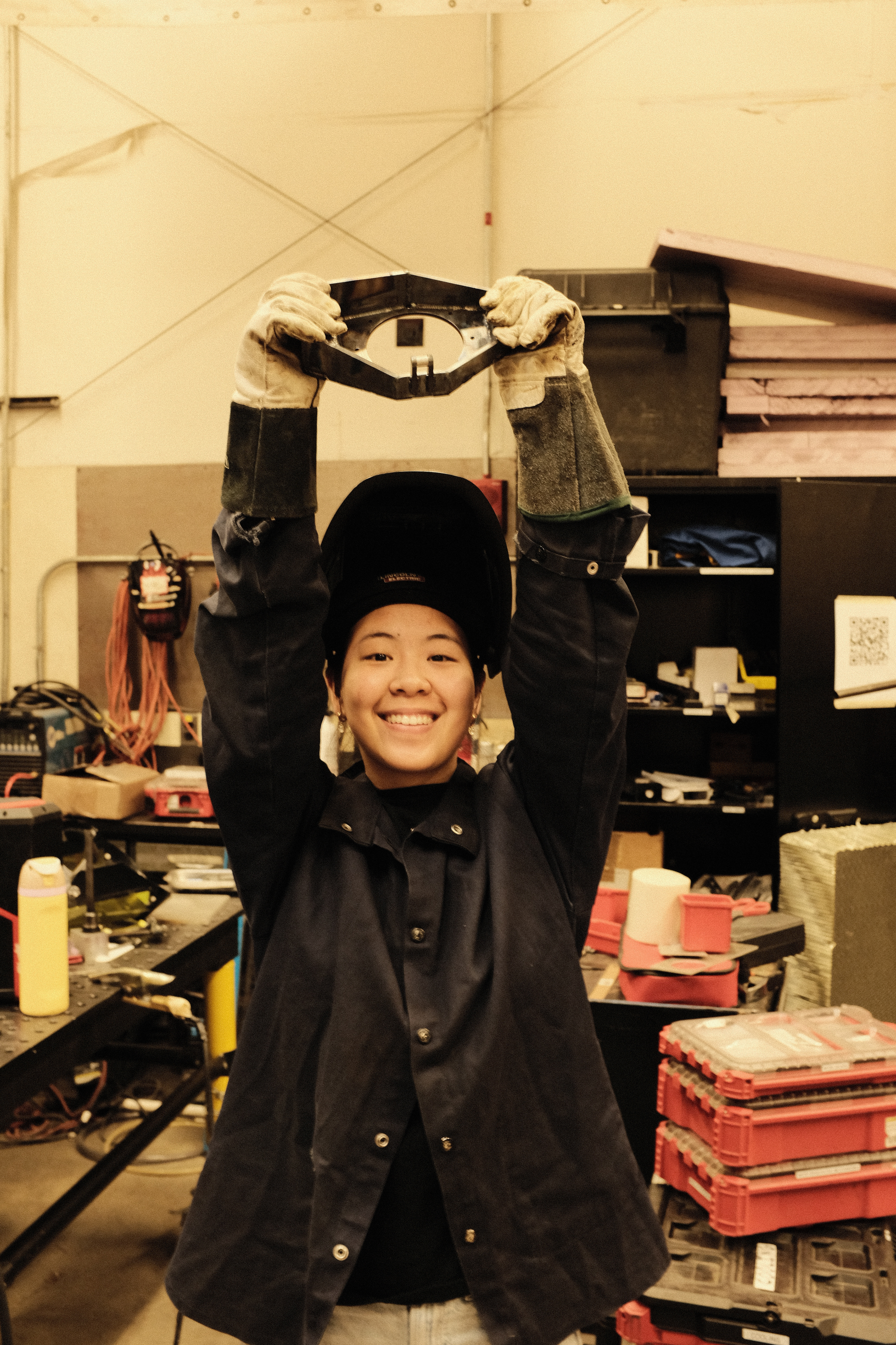
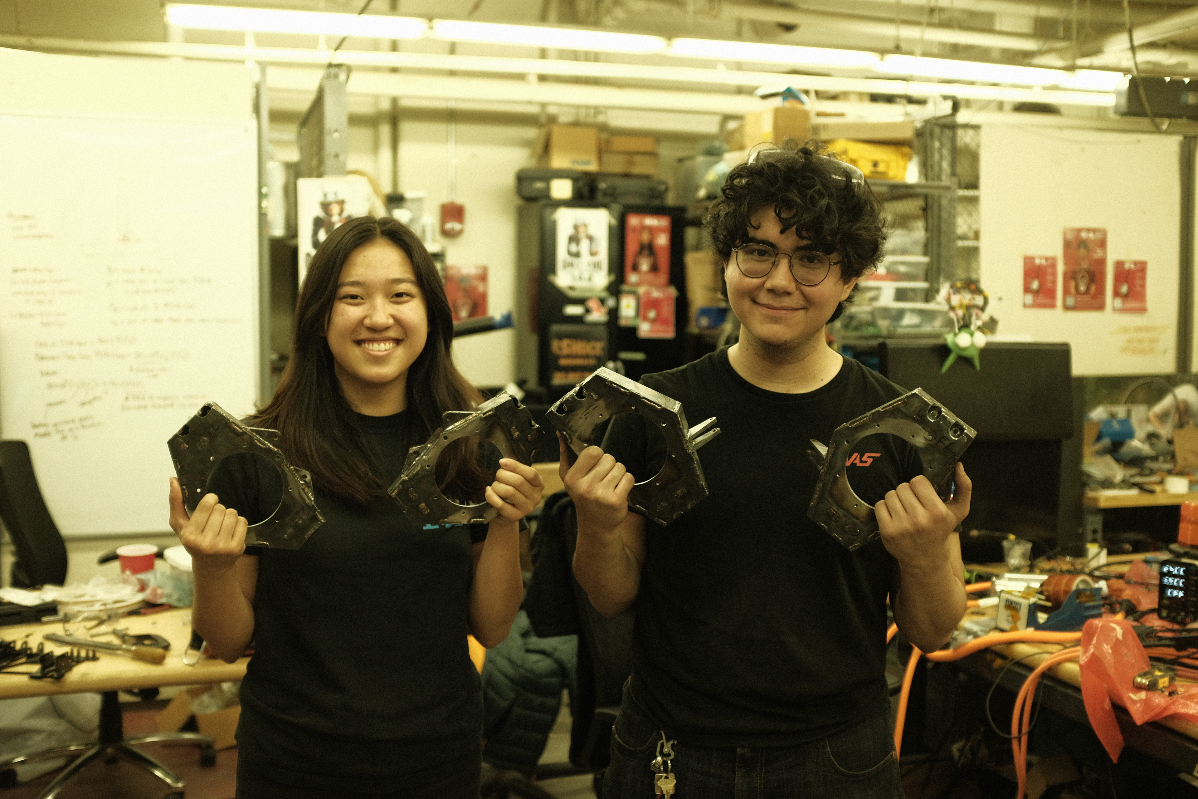
Mia after welding the first upright, and Debbie and I after finishing up the uprights. Getting to this stage took three days of design, two days of analysis, and two days of welding. In total, I spent 120 hours in shop over the course of these days getting this done.
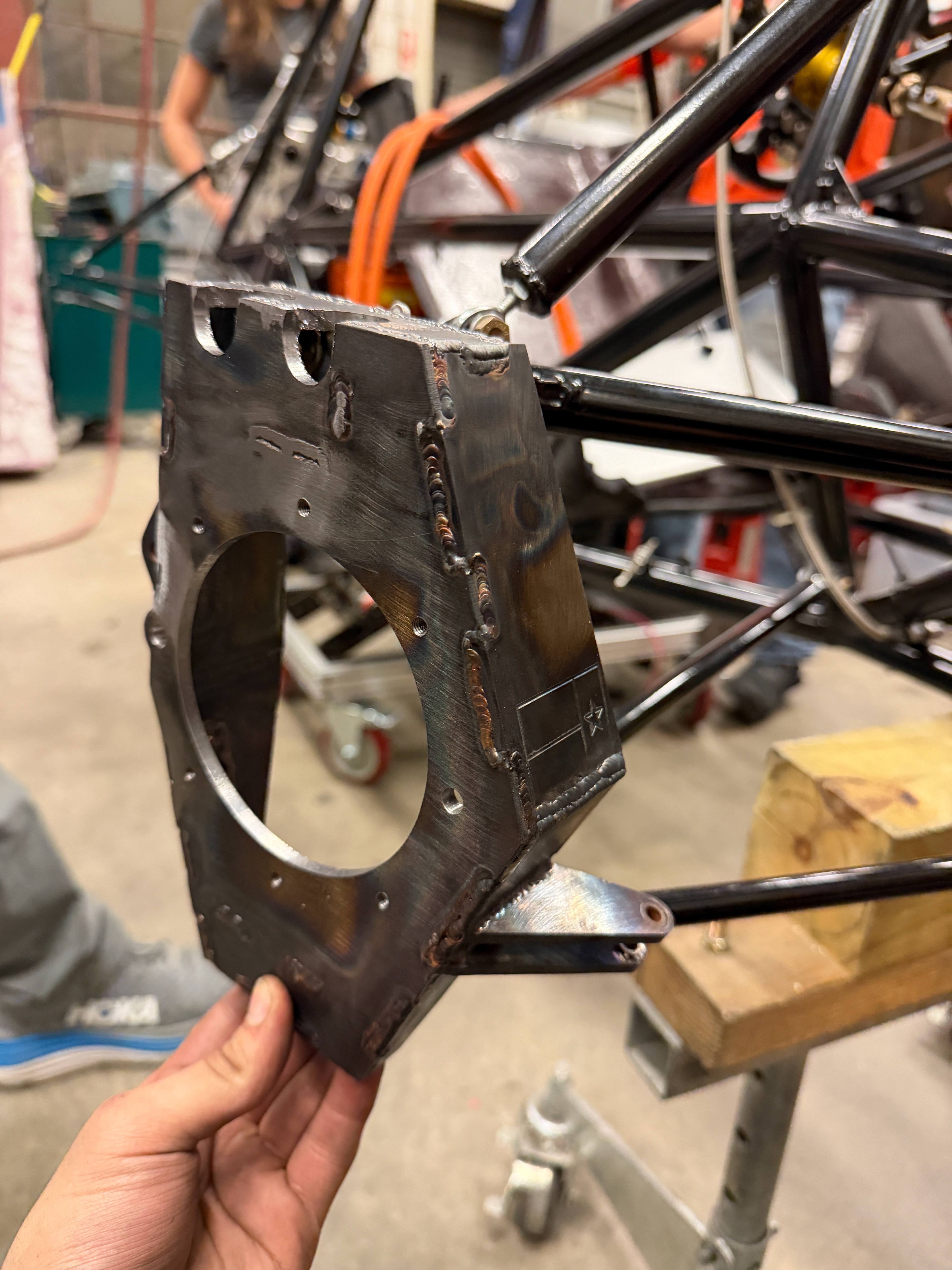
However, disaster struck once more. We learned that the gear carriers were once again delayed by the machine shop we outsourced them to, meaning that even with these uprights, we could not get the car to drive in time for Hybrid. Unless...
Enter: Project Hail Mary 2
(The one where we literally graverobbed MY25's gearboxes)
Enter: Project Hail Mary 2
(The one where we literally graverobbed MY25's gearboxes)
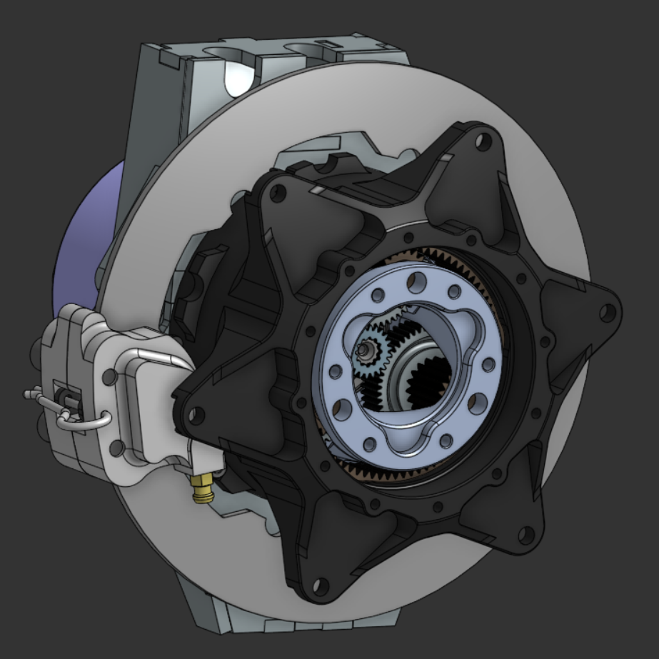
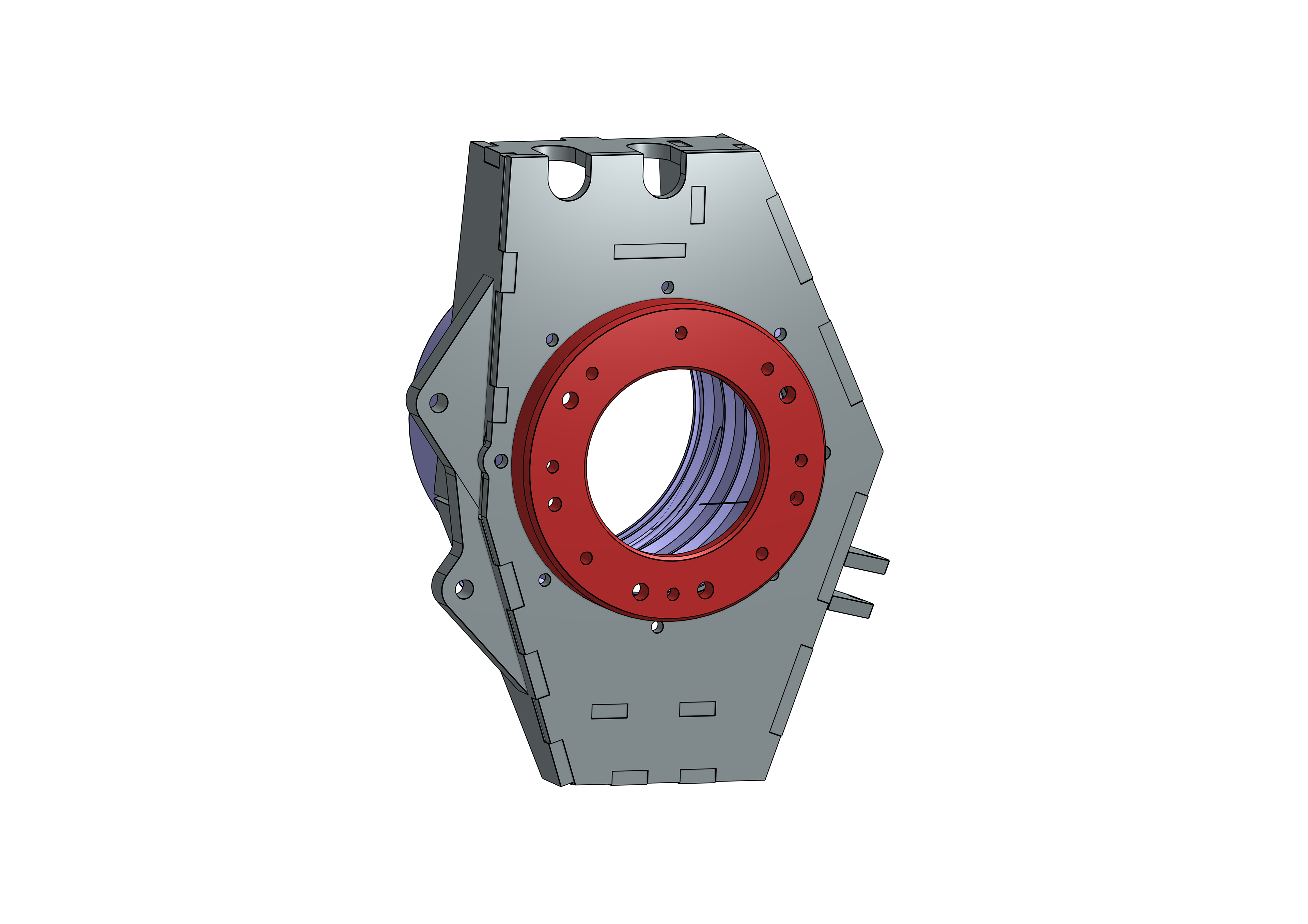
With no gearbox, we realized that we could adapt the gearboxes from MY25 just to get the car running for competition. This made the uprights much more complex: The adapter puck would need precision bores for the carrier and lip seal, and an interface for the motors, but it was doable. With a weekend and a refreshed supply of Red Bull, I got to work.
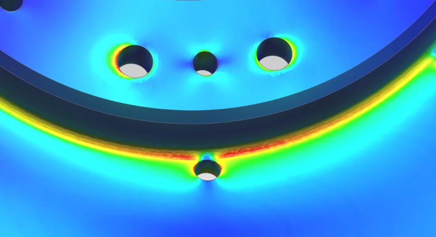
Initial work began with FEA to make sure this puck idea would actually work. So long as it was made of 4140, stress was low enough that we would be fine.
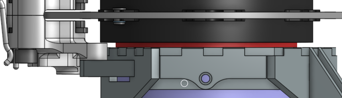
The puck would weld to the front of the upright using an alignment jig. We also needed to grind off and weld on new brake tabs.
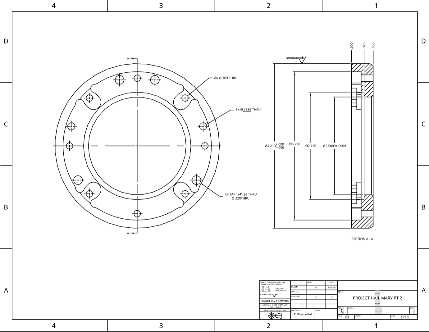
My internal drawing of the puck. The bore tolerances were quite tight, and I had to do it in a weekend. The OD was also a sealing interface, which made things even more fun.
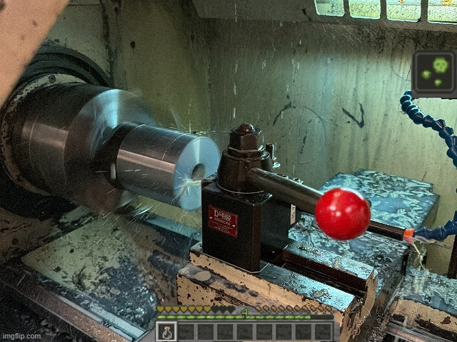
To make the pucks, I precision machined the internal and external bore on a large piece of 4140 on the lathe, followed by parting off. After that, I had programmed the VF2 to machine the 3d internal geometry for the motor mounting. In the end, I operated the lathe for 18 hours, only stopping to sleep and eat. It definitely didn't help that I was beginning to develop a coolant allergy from so many hours in the shop.
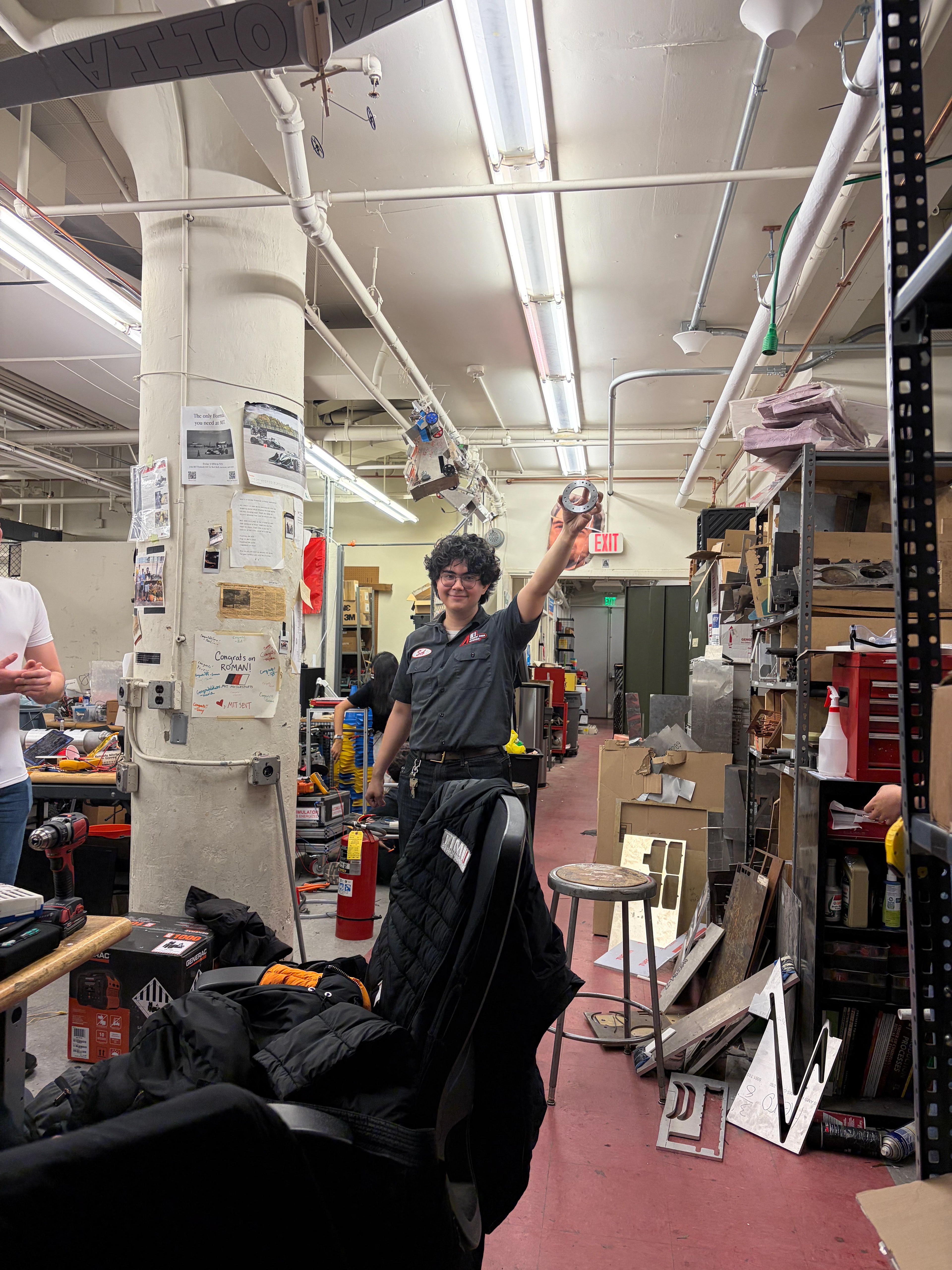
It was nice getting the first puck done, at a completely reasonable hour that definitely wasn't 6 in the morning.
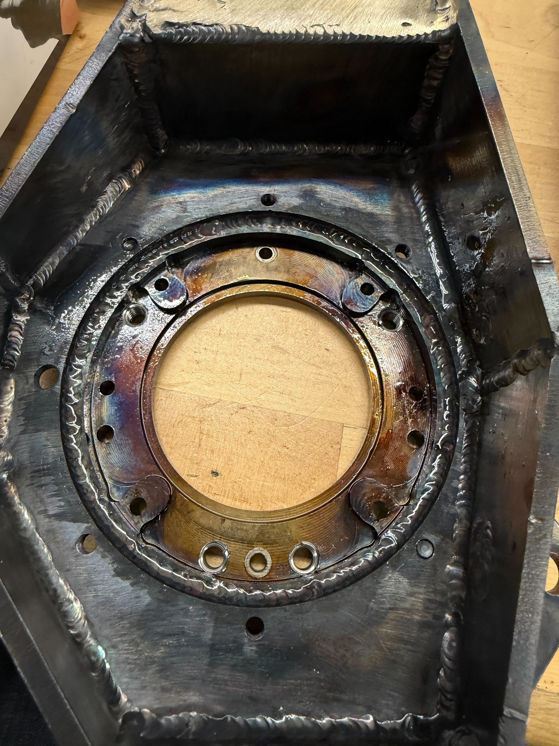
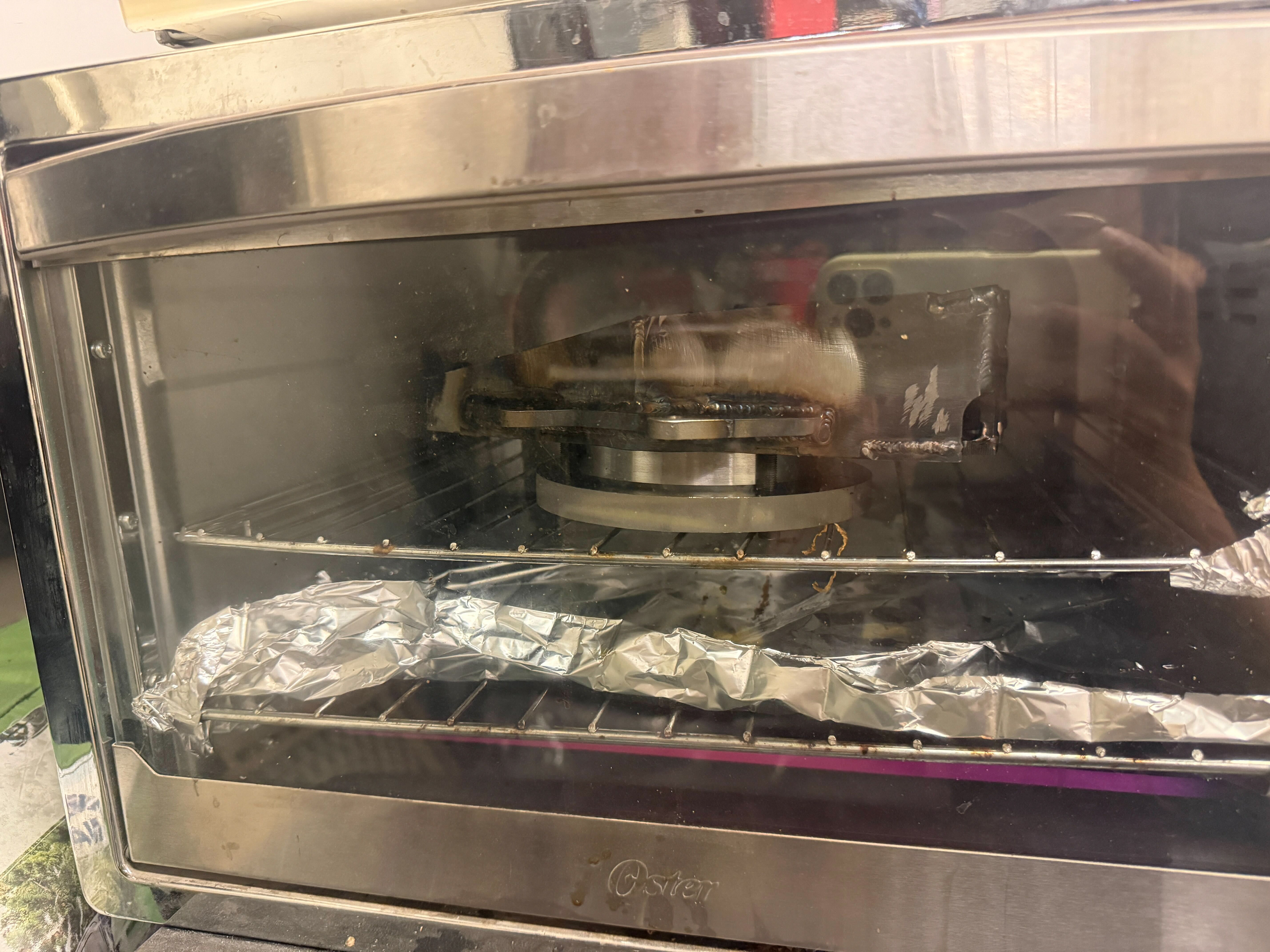
After that, welding began, once again courtesy of Mia Chen '27. Due to the fact we were welding 4140 to 4130, we had to preheat the components and let the welded components cool in a fire blanket to prevent weld cracking.
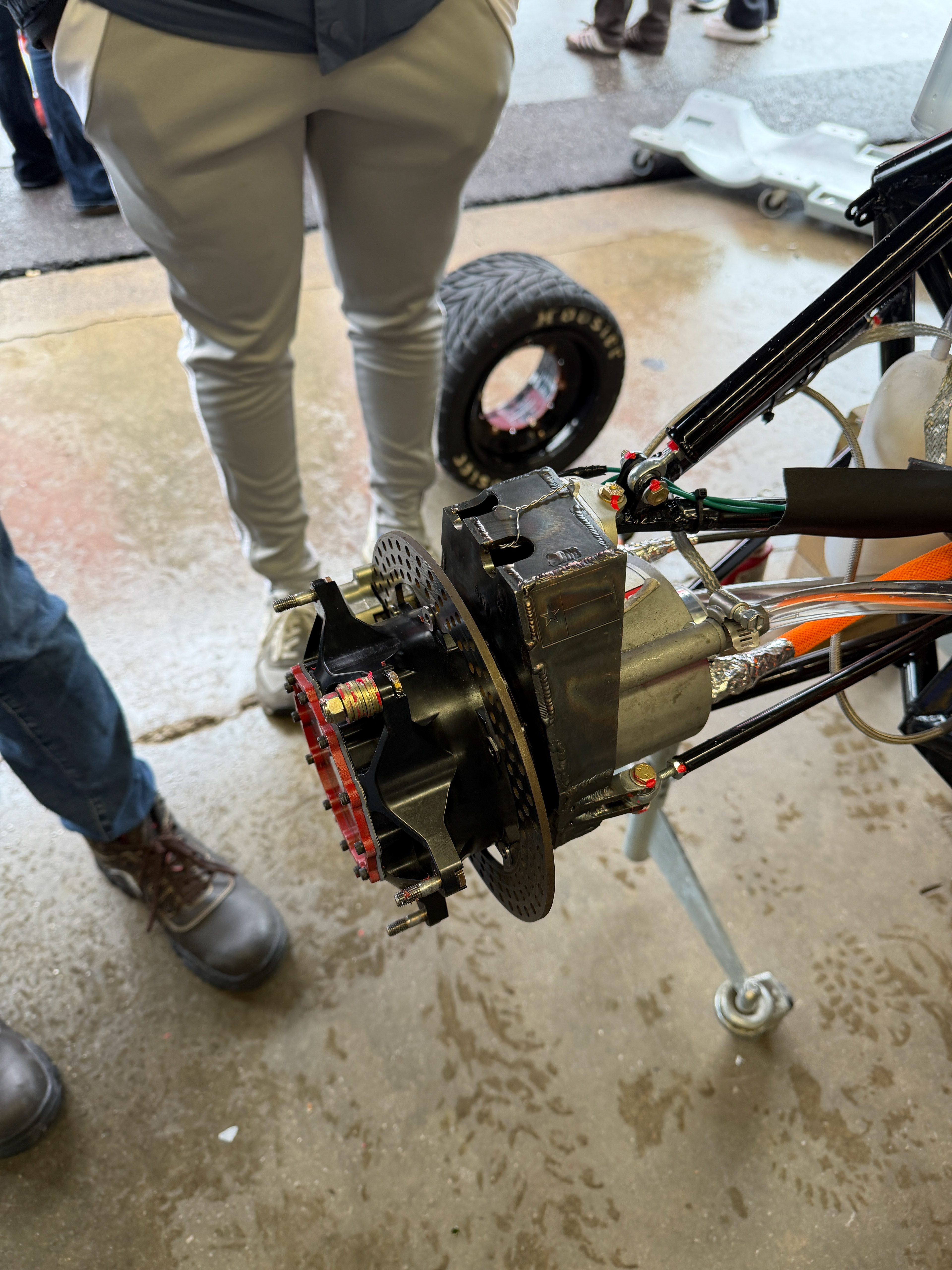
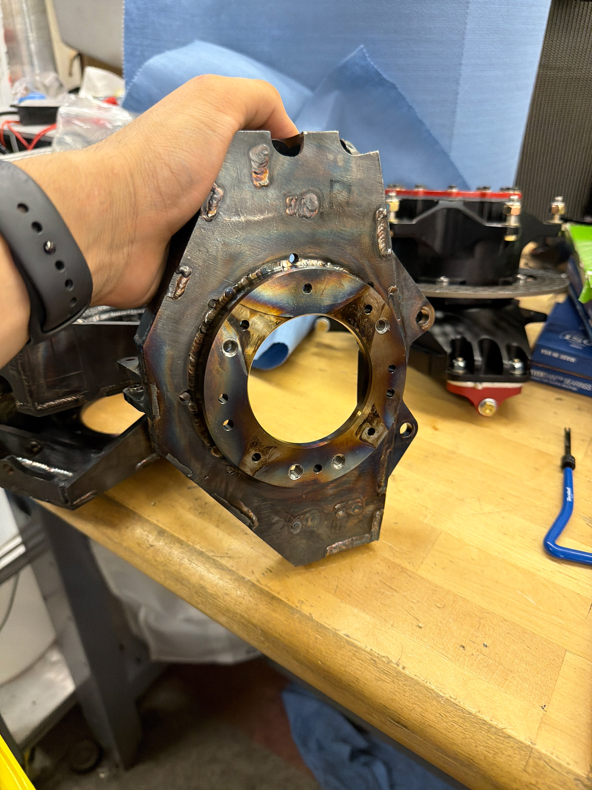
In the end, we got it done, and MY25.6 was able to drive and attend Hybrid. I don't think I've ever worked this hard in my life, but in the end, I gave the team the ability to test, and most importantly, hope.
Worth it.
Worth it.